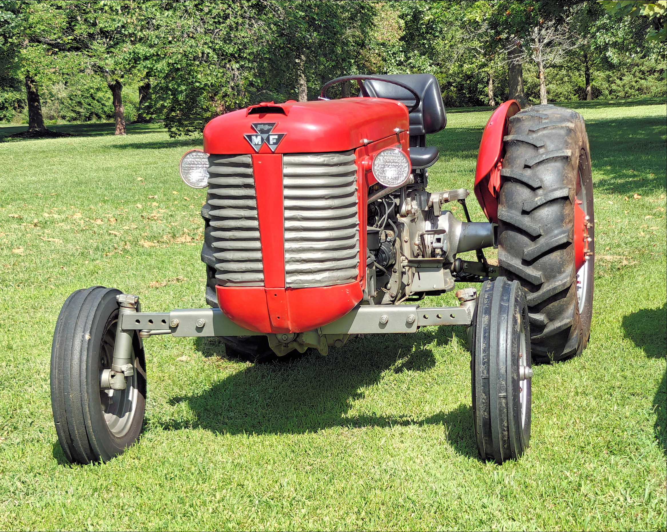
I bought this 1960 Massey Ferguson Model 65 instead of a “compact tractor” to use around the property for landscaping and mowing.
The clutch was sloppy and I had a hard time engaging the PTO.
I removed the clutch lever and pivot from the tractor. The clutch pivot is held on with two bolts that protrude into the tractor below the gear oil level. You can expect gear oil to pour out of the bolt holes when you remove them. You can loosen the two bolts and remove one-at-a-time and rotate the clutch pivot plate and replace the bolt. If you work fast, you can do this without losing a lot of the gear oil.
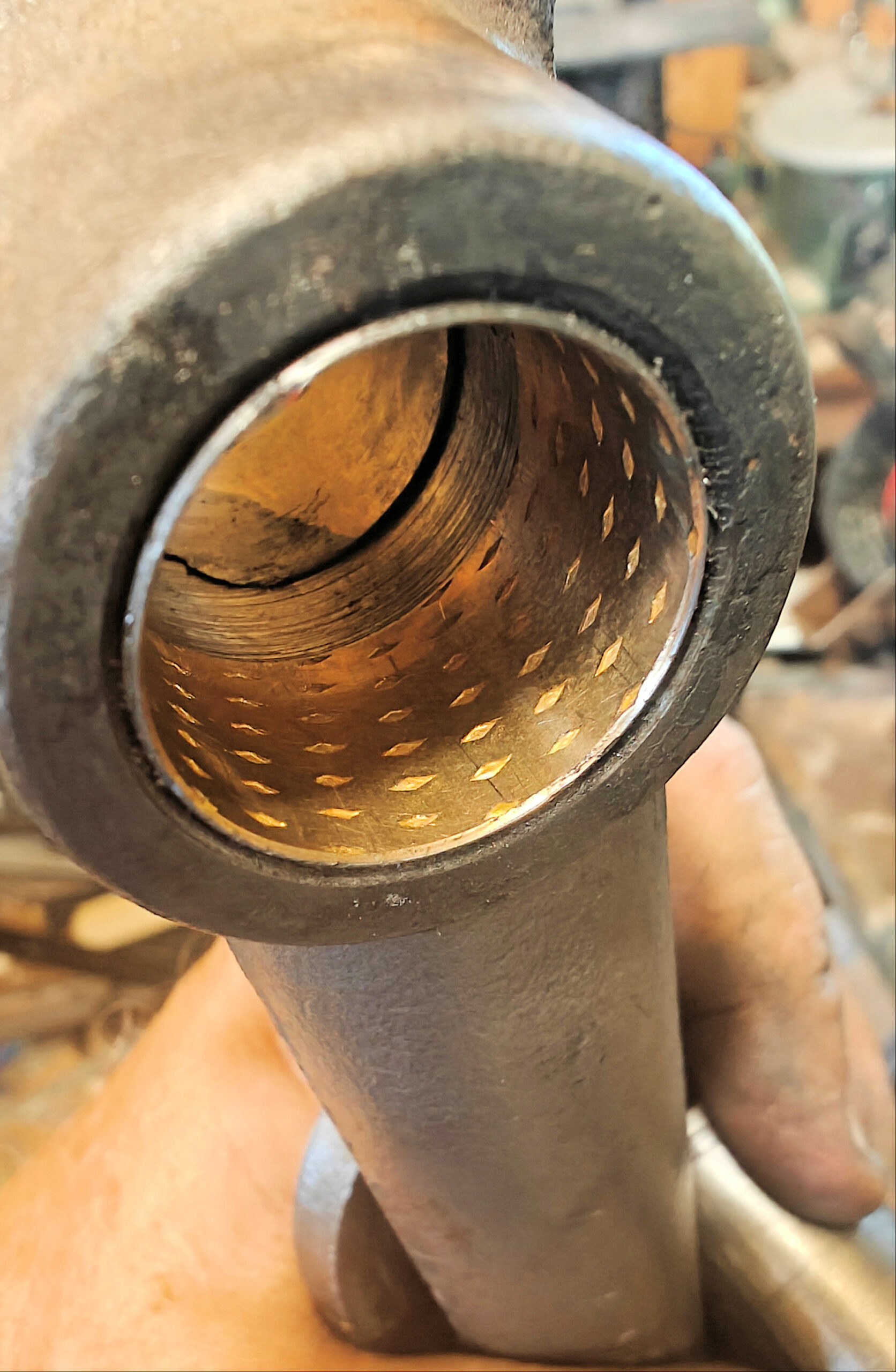
The clutch pedal bearings were worn almost completely through. The clutch pivot was worn and I was unable to find a new replacement online. I found one for the 165 but I was not sure it would work for my tractor.
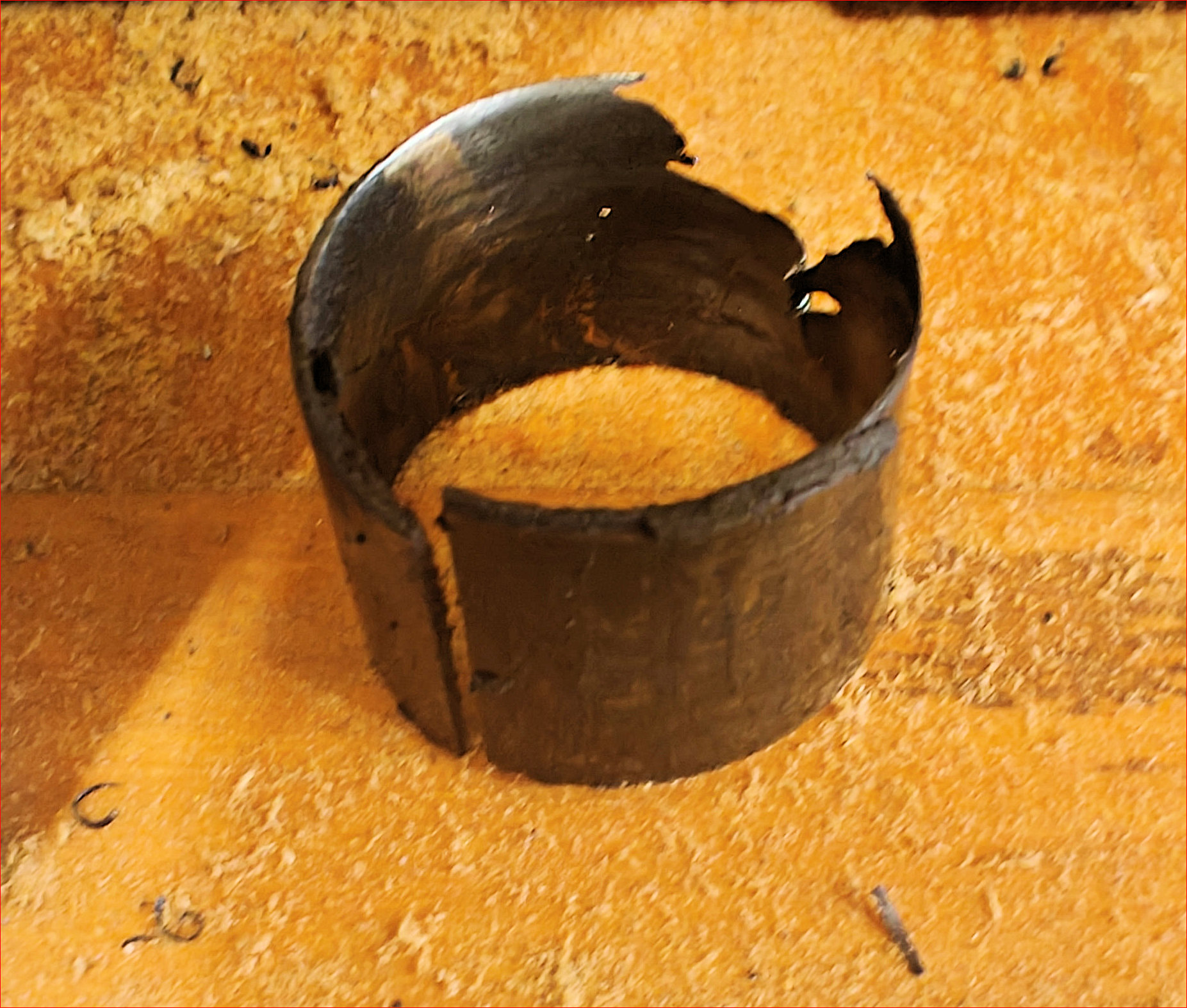
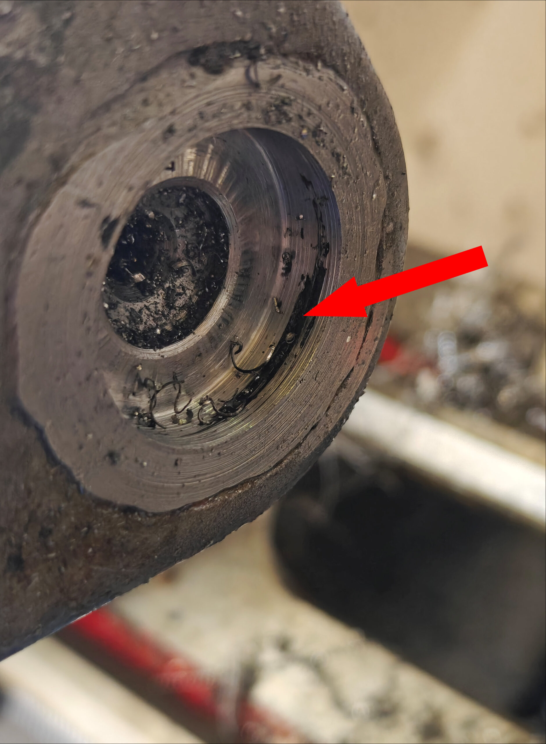
The clutch pivot bearings were paper thin.
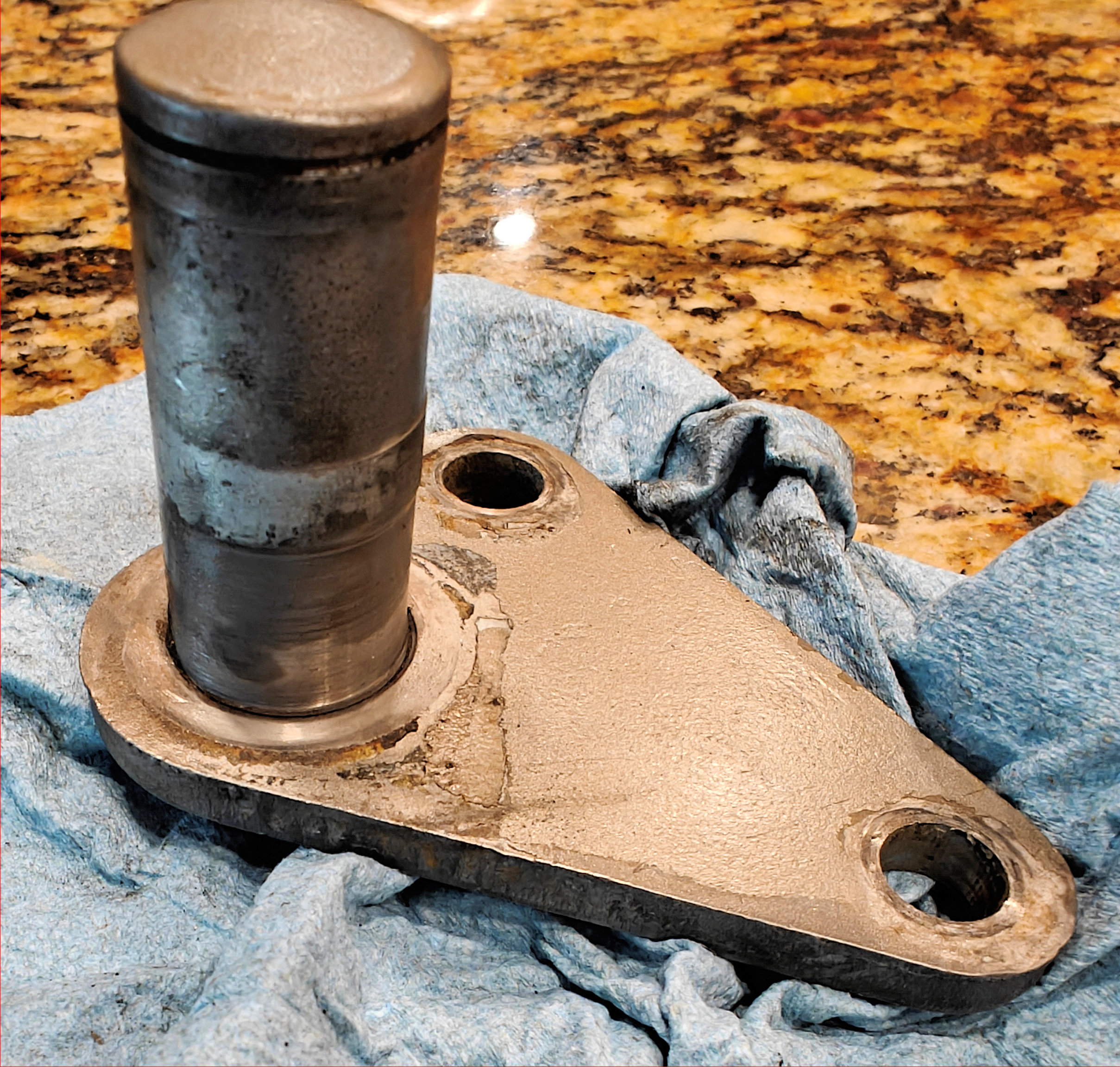
The clutch pivot was grooved. It may have been easier to make a new plate and shaft but I decided to try to remove the shaft from the plate and replace it.
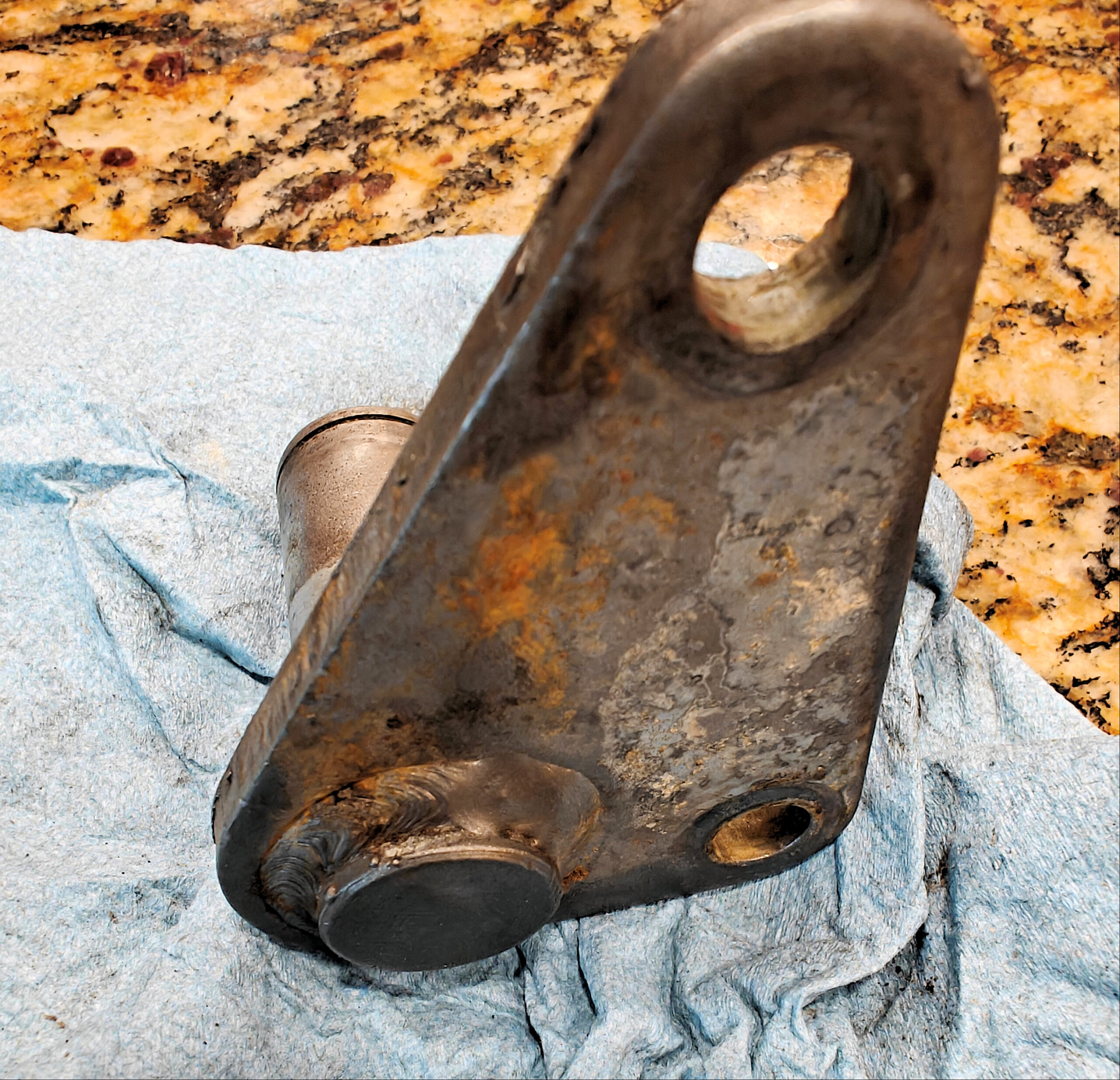
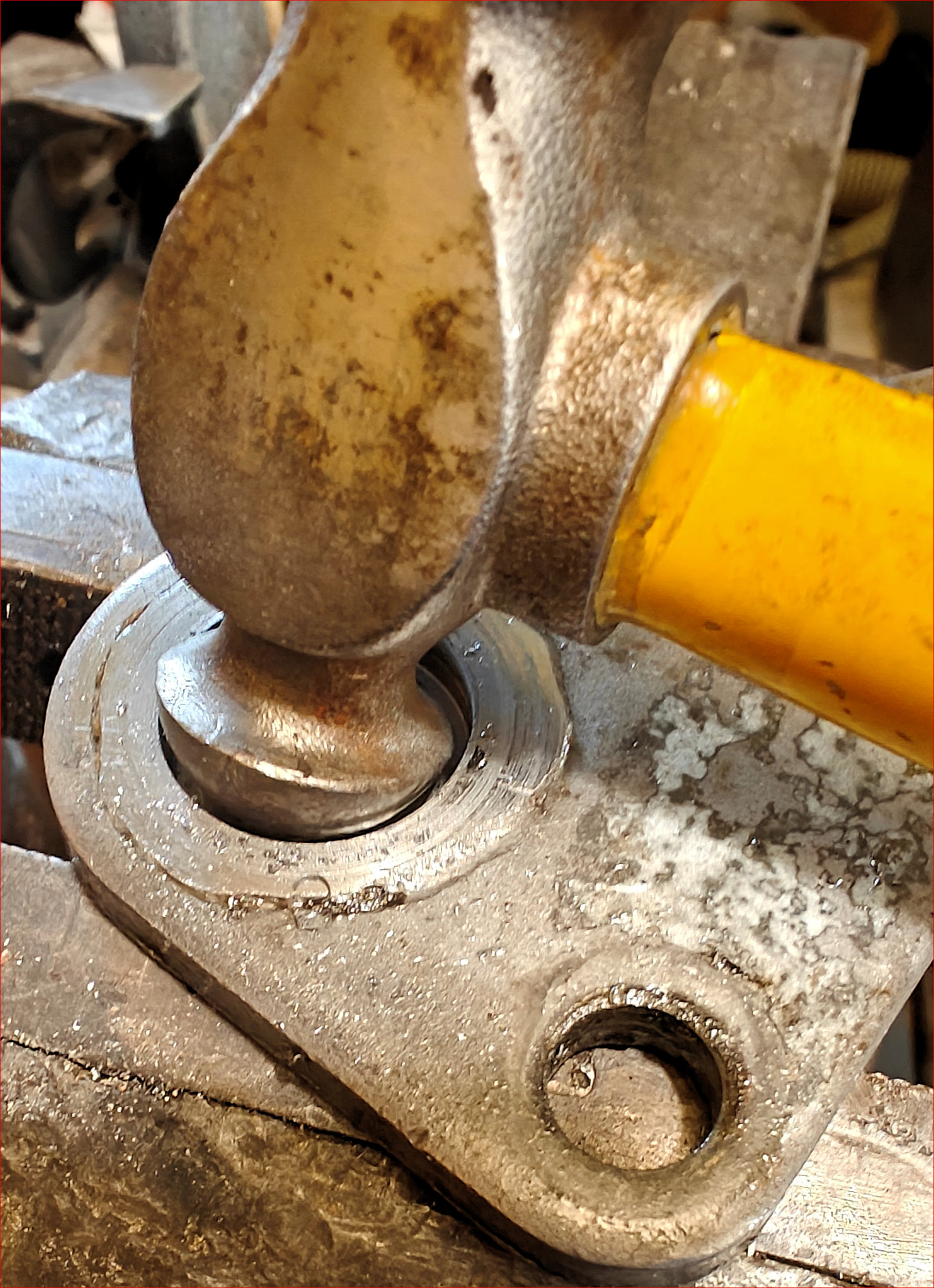
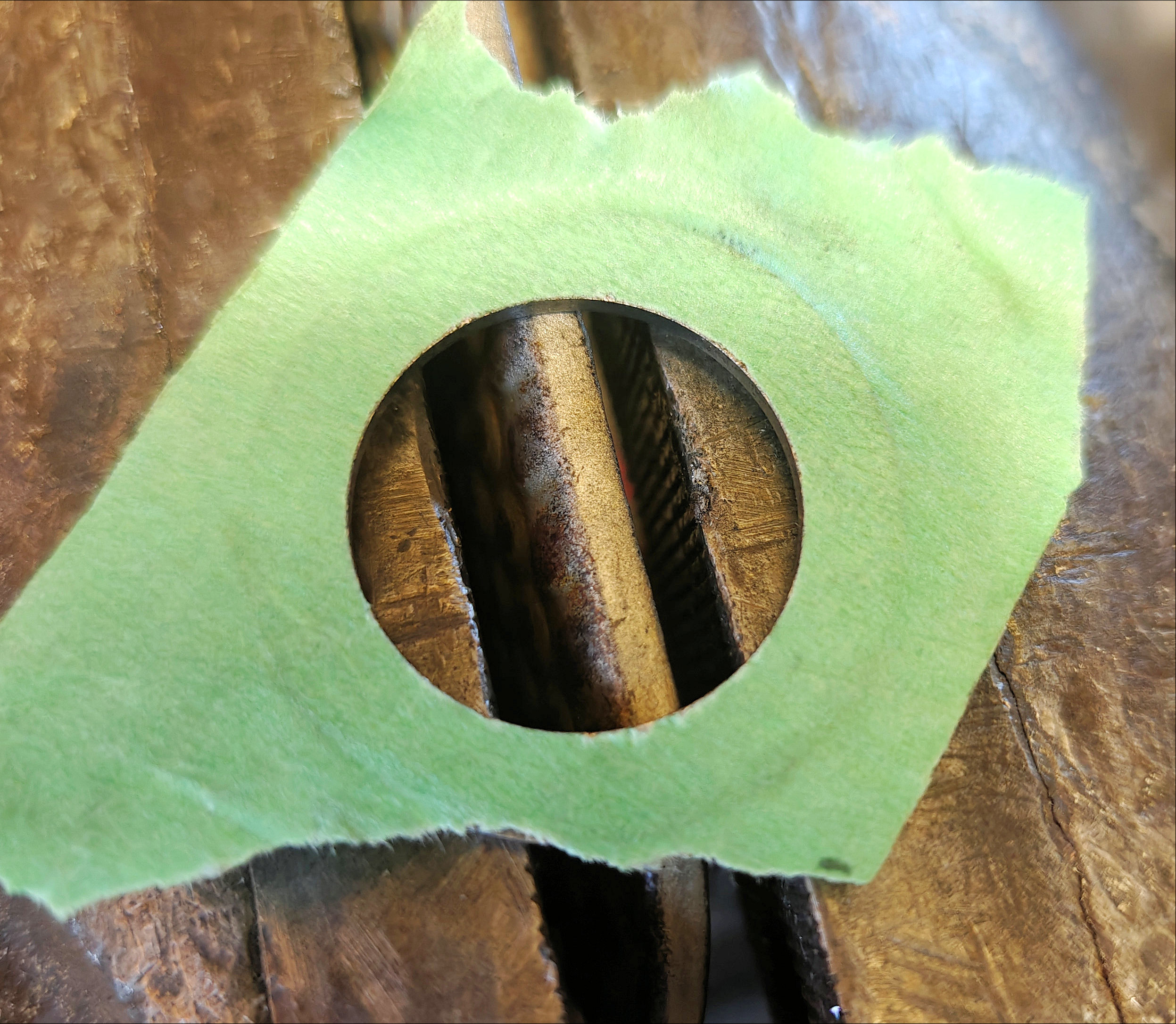
The shaft is welded through on the back.
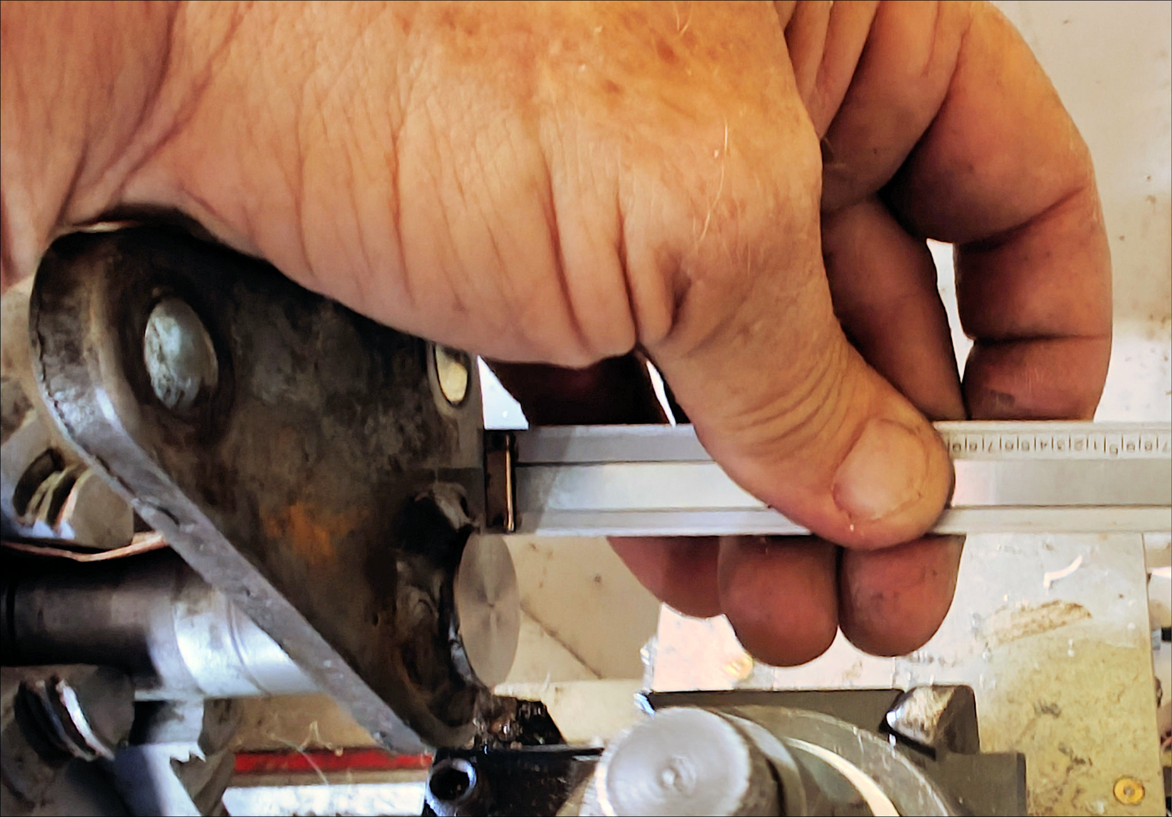
There is about 0.45-inches of shaft protruding through the back of the plate.
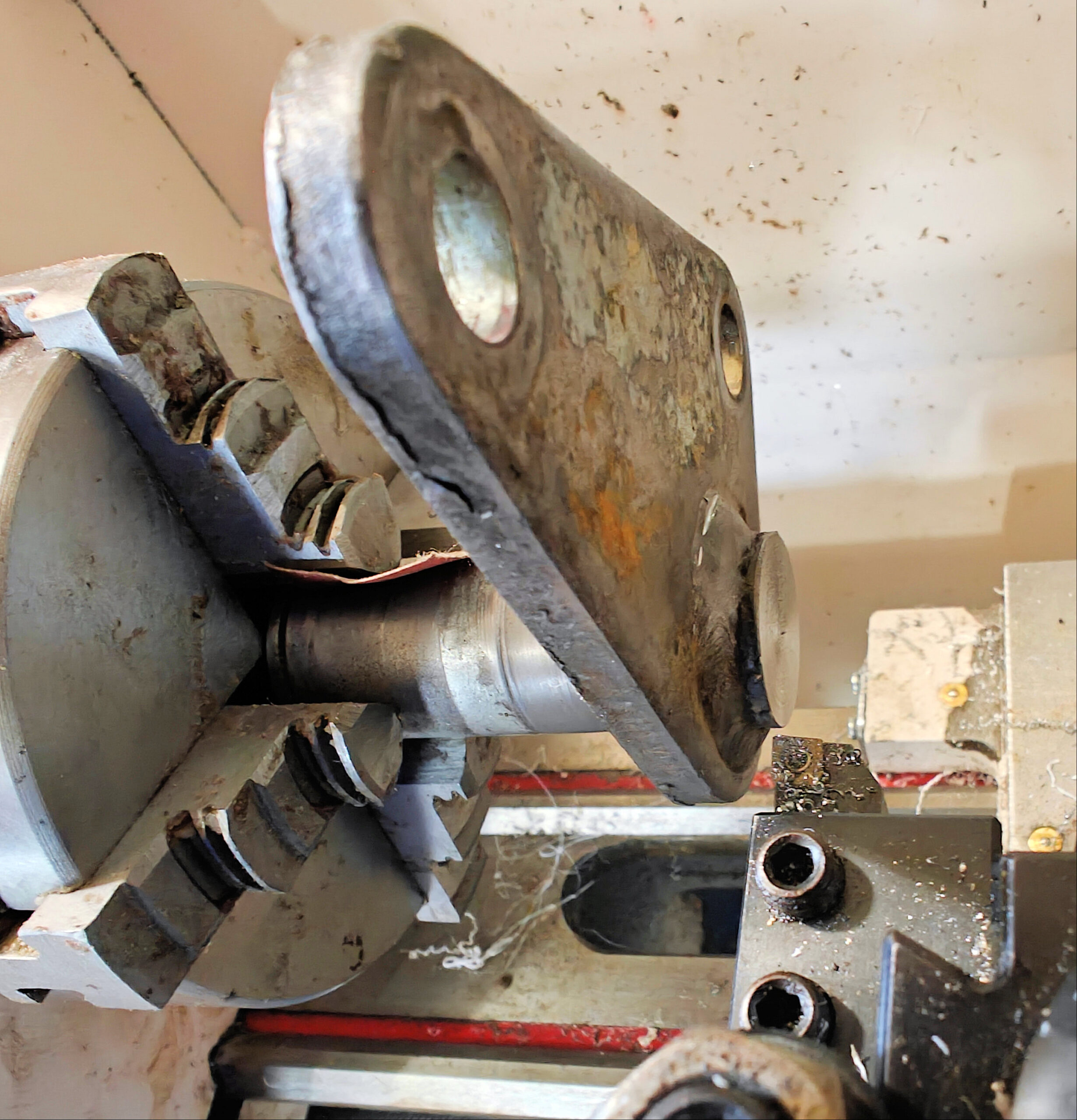
I chucked the pivot assembly in my hobby lathe. I used emory cloth to shim it where it was worn because it was the correct thickness.
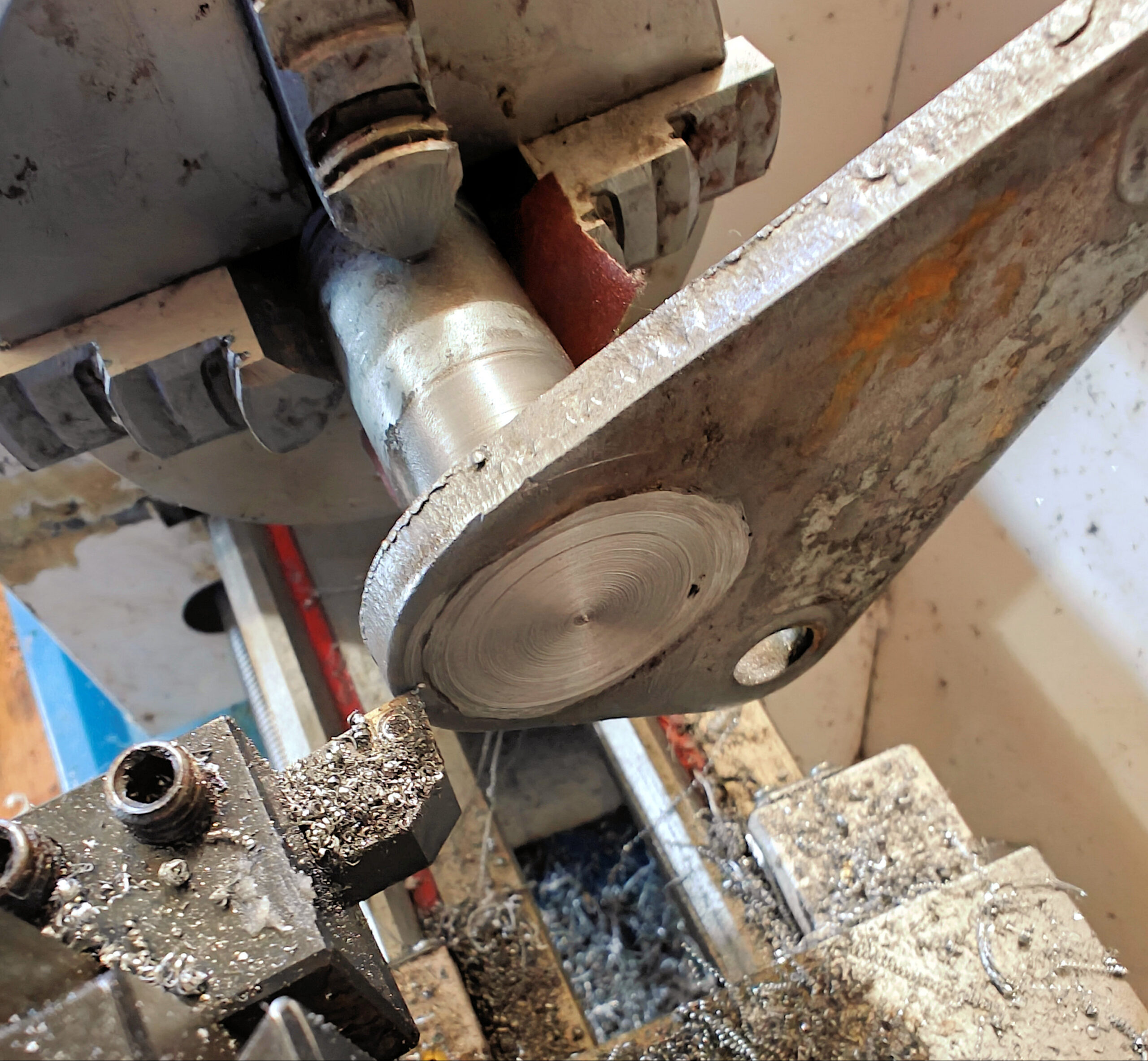
I took several passes to face off the old weld and shaft It was the best way I could think of to avoid interrupted cuts where the weld was uneven.
I center drilled and began boring out the old shaft.
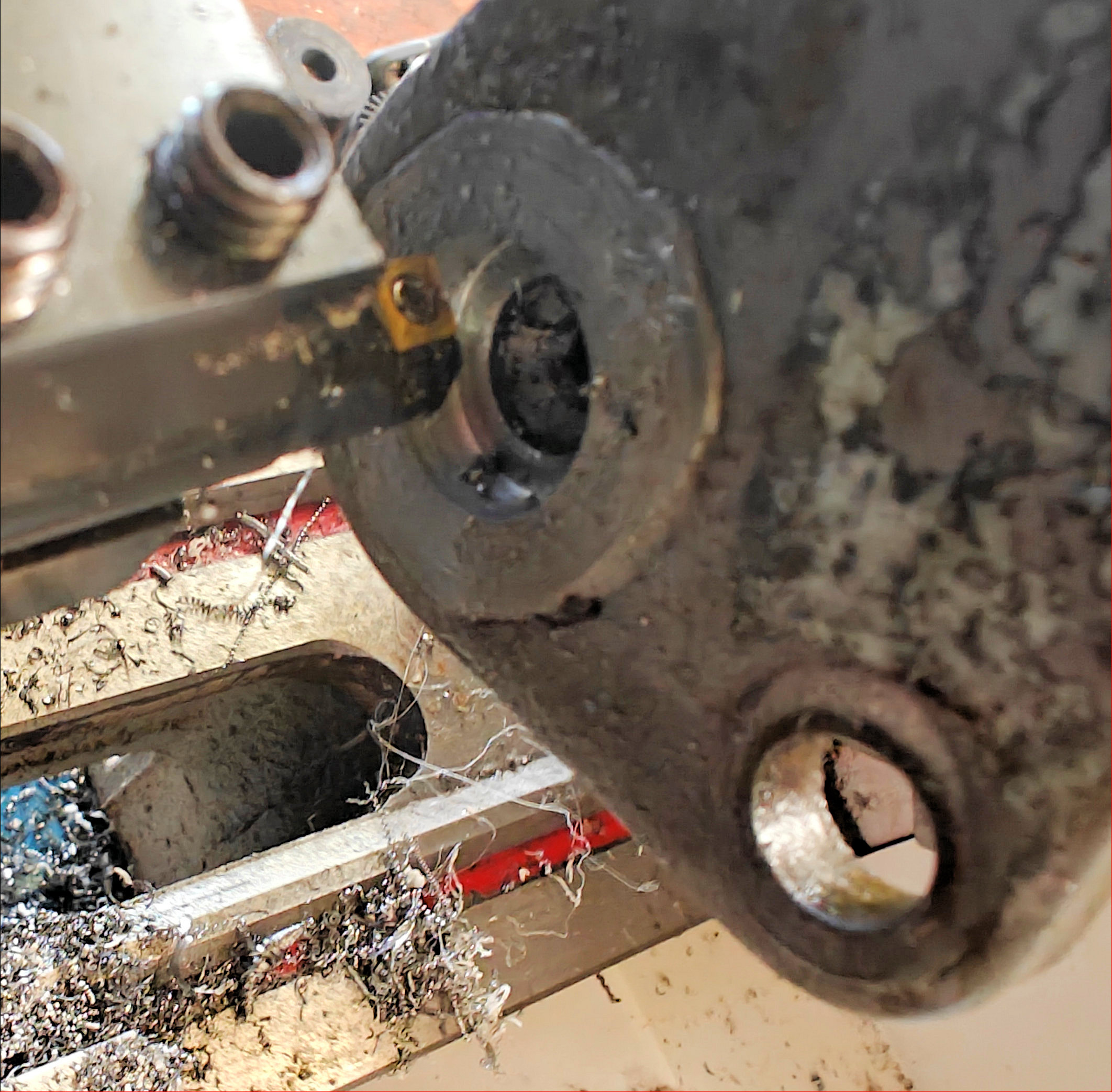
When I got to about 7/8-inch in diameter, I bored lightly to sneak up on the original shaft. I stopped when I saw the first edge of the shaft start to peel away.
I used a hammer and a punch to knock the remaining shaft from the plate.
The extra material around the shaft meant I did not enlarge the original hole and the new shaft would be in the same location as the original. I used a diamond bit on a Dremel tool to remove the remaining weld ridge from the plate.
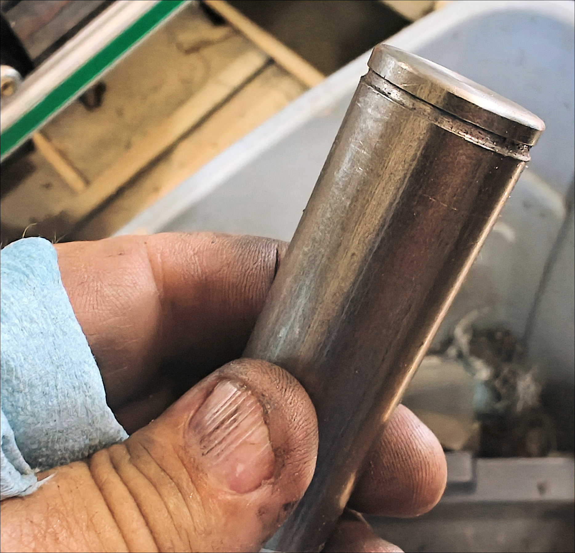
I made a new shaft out of 1-inch cold rolled steel. I tried cutting the snap ring groove with a parting tool but I wound up grinding a braised carbide tool to shape to create the groove.
I was only able to purchase one bearing at the local MF parts supplier so I put it toward the outside of the pedal assembly and kept the best of the old bearings for the inside. I ordered another bearing online and I will replace the inner bearing when it arrives.
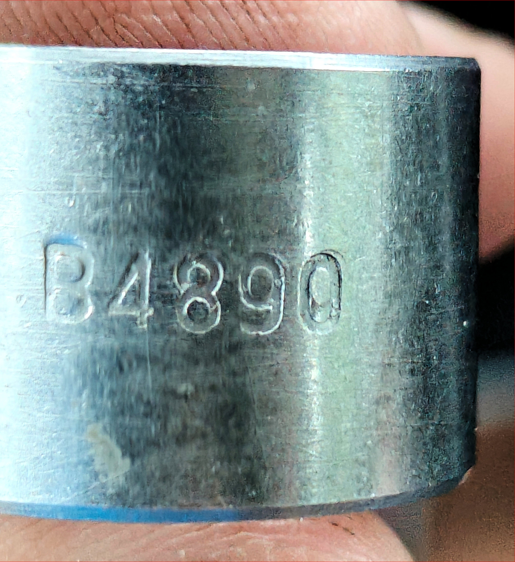
The bearings are 1-inch I.D. and 1 1/6-inch O.D steel with Oillite centers. There is a number stamped on the outside of the bearing but I was unable to cross reference it. They are split so you need to be careful installing them so they do not collapse.
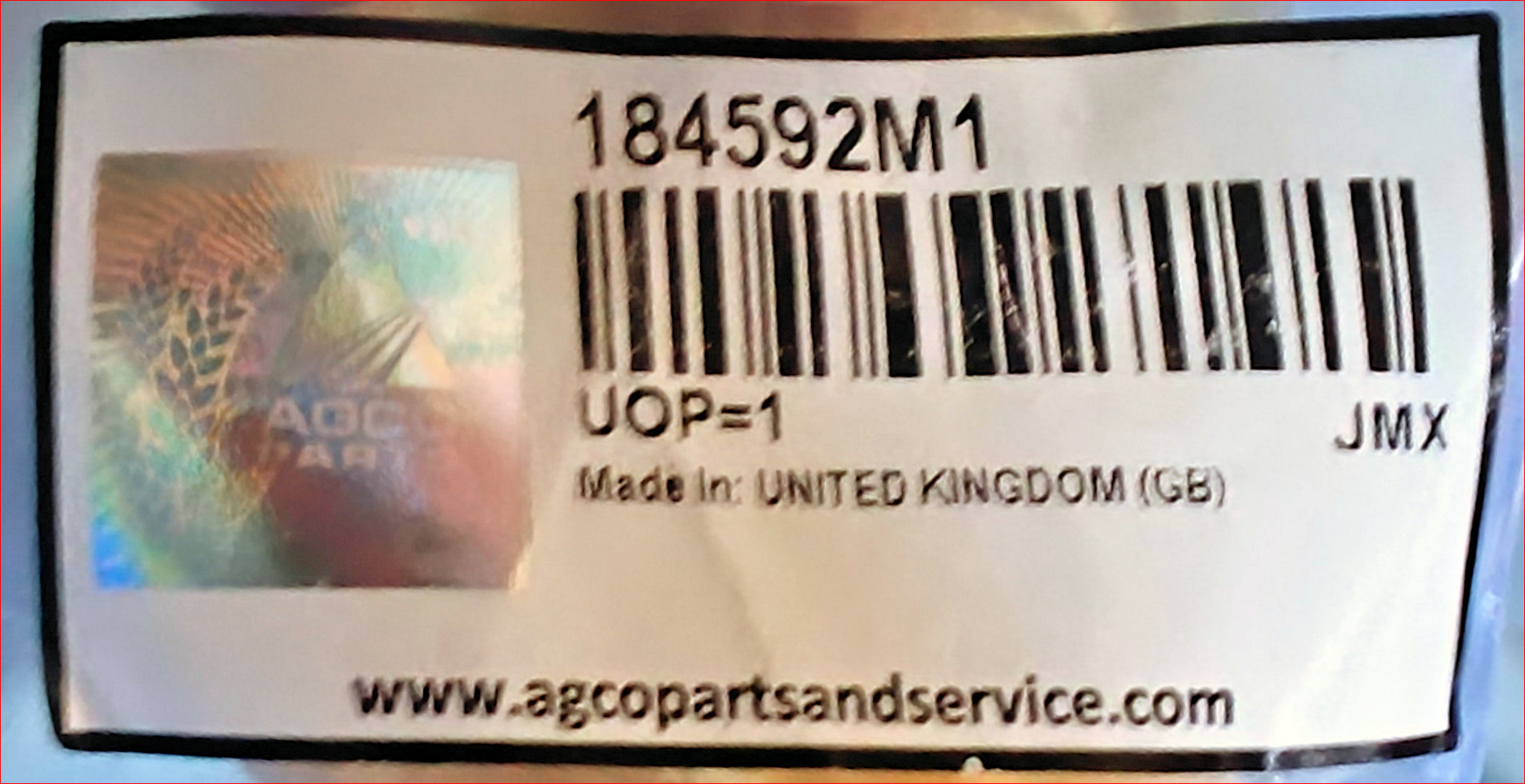
The Agco part number for the bearing is listed on the package.
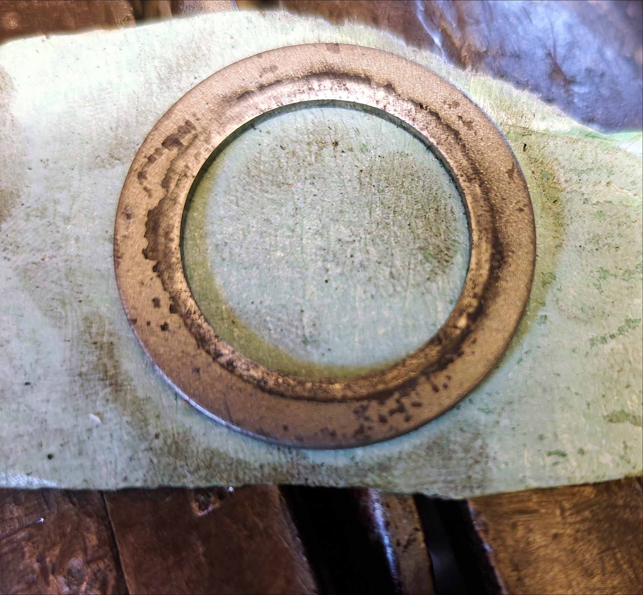
Before I tack welded the new shaft to the plate, I added a layer of masking tape to the snap ring washer for a little fudge in case the weld warped the part or caused the clearances to shrink when it cooled.
I cut the tape out of the center of the washer. I left the outer portion to keep the tape from shifting when I mounted the pedal on the clutch shaft.
I put everything together before tack welding with the wire-feed welder. It was an easy way to keep the shaft perpendicular to the plate and to get the correct spacing. After the shaft was tacked into place, I removed the clutch pedal to finish the weld.
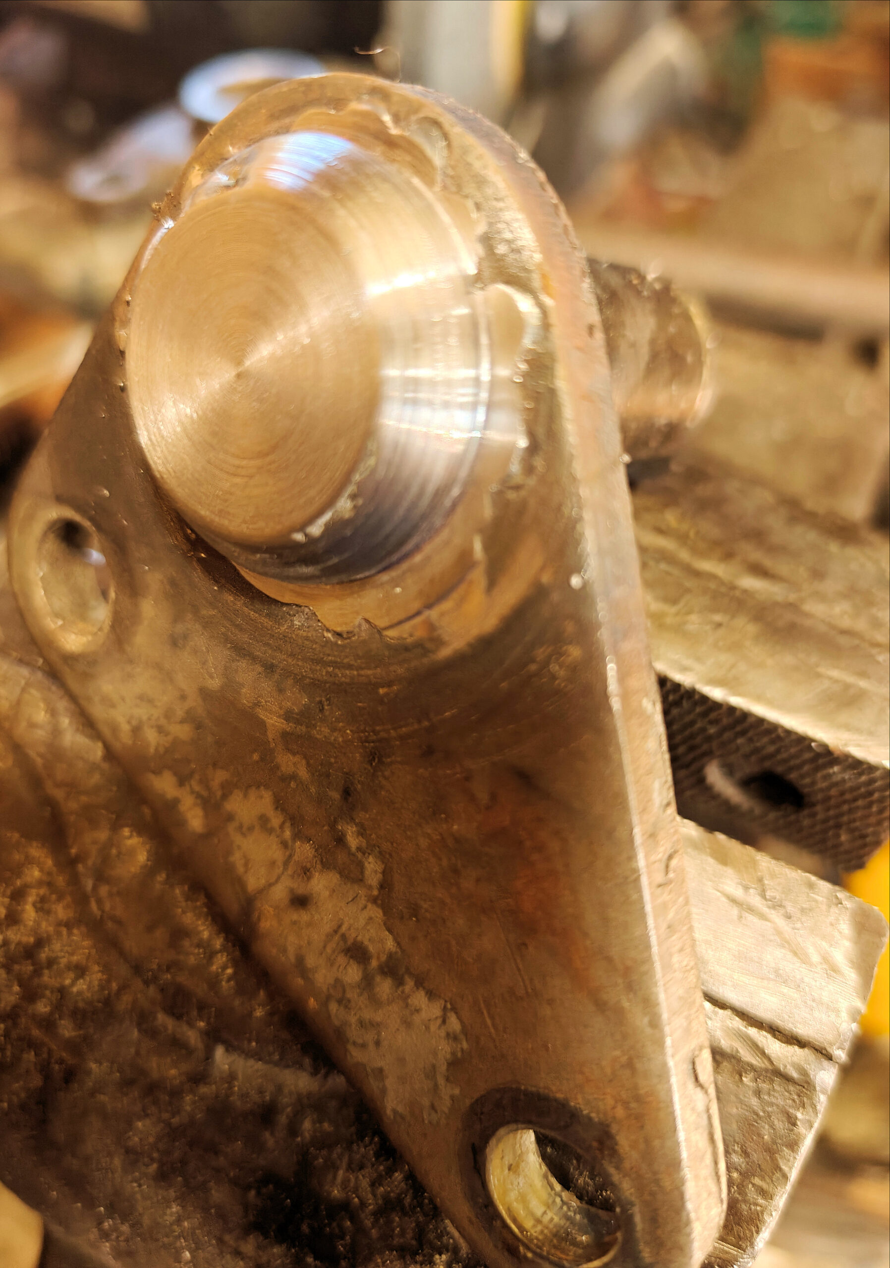
After everything was welded, I used the bandsaw to cut off the extral shaft material from the back of the plate and faced it off on the lathe. I also used the lathe to dress up the weld.
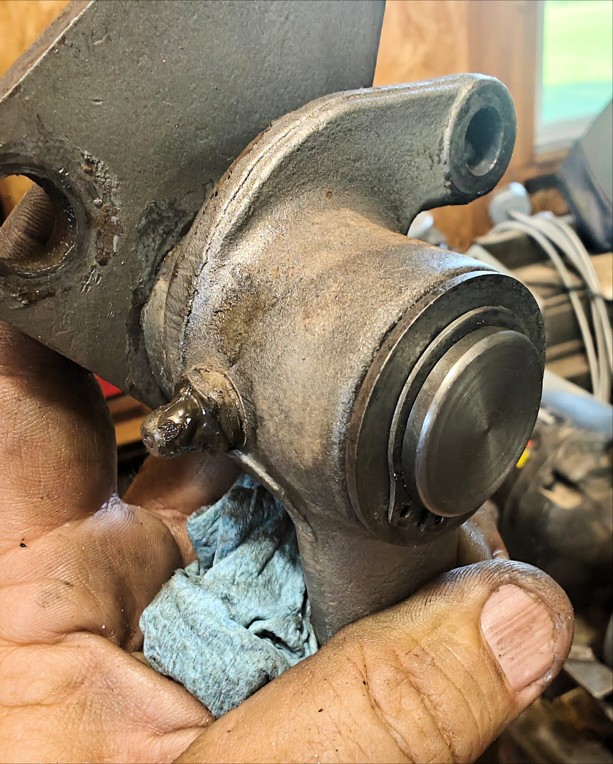
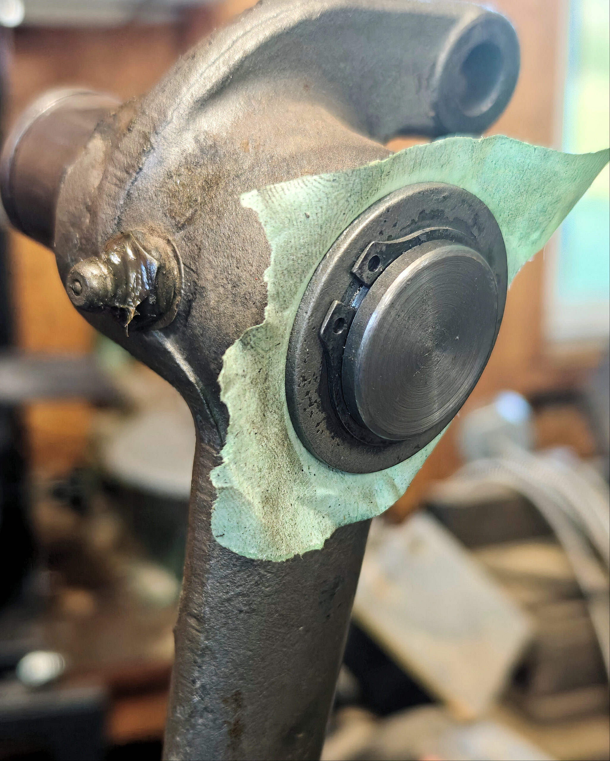
This is the final assembly.
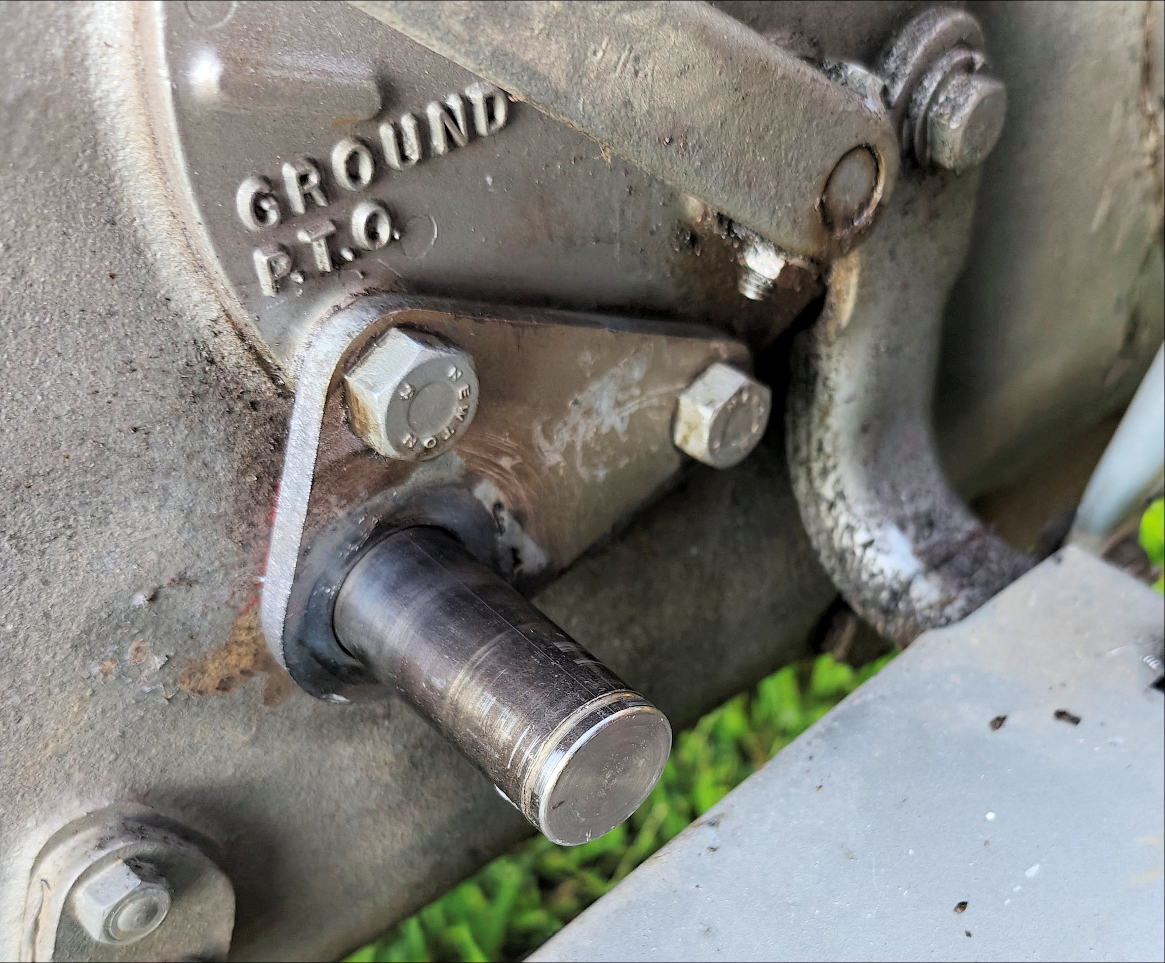
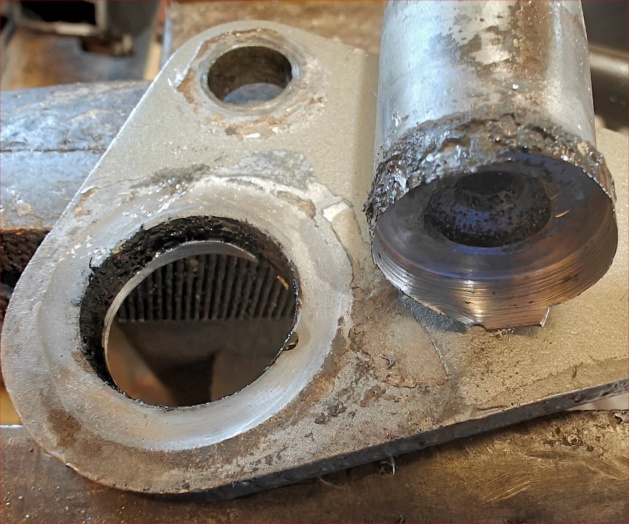
This is the new pivot bolted on to the tractor.
I also replaced one of the clevis rod-end connectors and both the clevis pins and cotter pins. I wound up creating clevis pins out of long 3/8-inch shouldered bolts because it was faster to make them than to drive to the hardware store.
The new pedal assembly works like new.

Leave a Reply